Bipolar power supply from ready-made Chinese dc-dc step down LM2596 modules. Homemade power supply from a Chinese voltammeter Laboratory power supply from modules aliexpress circuit diagram
Quite high parameters are declared, and the cost of the finished module is less than the cost of the parts included in it. The small size of the board is attractive.
I decided to purchase a few and test them out. I hope my experience will be useful to less experienced radio amateurs.
I bought LM2596 modules on Aliexpress, as in the photo above. Although the site showed solid capacitors with a voltage of 50 V, the capacitors are ordinary, and half of the modules have capacitors with a voltage of 16 V.
It can hardly be called a stabilizer...
You might think that it is enough to take a transformer, a diode bridge, connect a module to them, and we have a stabilizer with an output voltage of 3...30 V and a current of up to 2 A (short-term up to 3 A).That's exactly what I did. Without load everything was fine. A transformer with two windings of 18 V and a promised current of up to 1.5 A (the wire was clearly too thin by eye, and so it turned out).
I needed a +-18 V stabilizer and I set the required voltage.
With a 12 Ohm load the current is 1.5 A, here is the waveform, 5 V/cell vertical.
It can hardly be called a stabilizer.
The reason is simple and clear: the capacitor on the board is 200 uF, it serves only for normal operation DC-DC converter. When voltage was applied to the input from a laboratory power supply, everything was fine. The solution is obvious: you need to power the stabilizer from a source with low ripples, i.e. add a capacitance after the bridge.
Fighting ripples
Here is the voltage with a load of 1.5 A at the input of the module without an additional capacitor.Increased input capacity

With an additional 4700 uF capacitor at the input, the output ripple decreased sharply, but at 1.5 A it was still noticeable. When reducing the output voltage to 16V, the ideal straight line (2V/cell).

The voltage drop across the DC-DC module must be at least 2…2.5 V.
Now you can watch the ripples at the output of the pulse converter.

Small pulsations with a frequency of 100 Hz modulated with a frequency of several tens of kHz are visible.
LC filter at output
The Datasheet on the LM2596 recommends an additional LC filter on the output. That's what we'll do. As a core, I used a cylindrical core from a faulty computer power supply and wound the winding in two layers with 0.8 mm wire.
The board shows in red the location for installing the jumper - common wire two channels, the arrow is the place for soldering the common wire, if you do not use terminals.
Let's see what happened to the HF pulsations.

They are no more. Small pulsations with a frequency of 100 Hz remained.
Not ideal, but not bad.
I note that as the output voltage increases, the inductor in the module begins to rattle and RF interference at the output sharply increases; as soon as the voltage is slightly reduced (all this with a load of 12 Ohms), the interference and noise completely disappear.
Final circuit diagram for connecting LM2596 modules
The scheme is simple and obvious.With a long-term load of 1 A current, the parts heat up noticeably: the diode bridge, the microcircuit, the module choke, most of all the choke (additional chokes are cold). Heating to the touch is 50 degrees.
When operating from a laboratory power supply, heating at currents of 1.5 and 2 A is tolerable for several minutes. For long-term operation with high currents, a heat sink to the microcircuit and inductor is desirable bigger size.
Installation
To mount the module, I used homemade “stands” made of tinned wire with a diameter of 1 mm.
This ensured convenient installation and cooling of the modules. The posts can get very hot when soldering and will not move like simple pins. The same design is convenient if you need to solder external wires to the board - good rigidity and contact.
The board makes it easy to replace the DC-DC module if necessary.
General view of the board with chokes from halves of some kind of ferrite core (inductance is not critical).
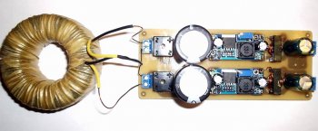
Despite the tiny dimensions of the DC-DC module, the overall dimensions of the board turned out to be comparable to an analog stabilizer board.

conclusions
1. A transformer with a high-current secondary winding or with a voltage reserve is required; in this case, the load current may exceed the current of the transformer winding.2. At currents of the order of 2 A or more, a small heat sink to the diode bridge and the 2596 microcircuit is desirable.
3. Power capacitor is desirable large capacity, this has a beneficial effect on the operation of the stabilizer. Even a large and high-quality container heats up a little, therefore a low ESR is desirable.
4. To suppress ripple with the conversion frequency, an LC filter at the output is required.
5. This stabilizer has a clear advantage over a conventional compensation one in that it can operate in a wide range of output voltages; at low voltages, it is possible to obtain an output current greater than what the transformer can provide.
6. Modules allow you to make a power supply with good parameters simply and quickly, bypassing the pitfalls of making boards for pulse devices, that is, they are good for beginner radio amateurs.
I have already done a couple of reviews of a similar thing (see photo). I ordered those devices not for myself, but for friends. Convenient device for homemade charging, and not only. I was also jealous and decided to order for myself. I ordered not only a volt-ampermeter, but also the cheapest voltmeter. I decided to assemble a power supply for my homemade products. I decided which one to put only after I had assembled the product completely. Surely there will be people who are interested.
Ordered on November 11th. There was a small discount. Although the price is low.
The parcel arrived for more than two months. The seller gave the left track from Wedo Express. But still the parcel arrived and everything works. Formally, there are no complaints.
Since I decided to integrate this particular device into my power supply, I’ll tell you about it in a little more detail.
The device came in a standard plastic bag, “pimpled” from the inside. 
IN this moment product unavailable. But this is not critical. There are now a lot of offers on Ali from sellers with good rating. Moreover, the price is steadily decreasing.
The device was additionally sealed in an antistatic bag. 
Inside is the device itself and wires with connectors. 
Keyed connectors. Don't insert it the other way around. 
The sizes are simply miniature. 
Let's look at what is written on the seller's page. 
My translation with corrections:
-Measured voltage: 0-100V
- Circuit supply voltage: 4.5-30V
-Minimum Resolution (V): 0.01V
-Current consumption: 15mA
-Measured current: 0.03-10A
-Minimum Resolution (A): 0.01A
Everything is the same, but very briefly, on the side of the product. 
I immediately took it apart and noticed that some minor parts were missing. 
But in previous modules this place was occupied by a capacitor. 
But their prices also differed to a greater extent.
All modules are similar like twins. There is also connection experience. The small connector is designed to power the circuit. By the way, at a voltage below 4V, the blue indicator becomes almost invisible. Therefore we follow technical specifications devices, we do not supply less than 4.5V. If you want to use this device to measure voltages below 4V, you need to power the circuit from a separate source through a “connector with thin wires”.
The current consumption of the device is 15mA (when powered by a 9V crown).
The connector with three thick wires is a measuring connector. 
There are two accuracy controls (IR and VR). Everything is clear in the photo. Resistors are ugly. Therefore, I don’t recommend twisting it often (you’ll break it). Red wires are terminals for voltage, blue for current, black wires are “common” (connected to each other). The colors of the wires correspond to the color of the indicator, so you won’t get confused.
Head chip without name. It once existed, but it was destroyed. 
Now I’ll check the accuracy of the readings using the P320 model setup. I applied calibrated voltages 2V, 5V, 10V, 12V 20V, 30V to the input. Initially, the device underestimated by one tenth of a volt within certain limits. The error is insignificant. But I adjusted it to suit myself. 
It can be seen that it shows almost perfectly. I adjusted it with the right resistor (VR). When rotating the trimmer clockwise, it adds, and when rotating counterclockwise, it decreases the readings.
Now I'll see how it measures current strength. I power the circuit from 9V (separately) and supply a reference current from the P321 installation 
The minimum threshold from which a current of 30mA begins to be correctly measured.
As you can see, it measures the current quite accurately, so I won’t twist the adjustment resistor. The device measures correctly even at currents greater than 10A, but the shunt begins to heat up. Most likely, the current limitation is for this reason. 
I also don’t recommend driving for a long time at a current of 10A.
I summarized more detailed calibration results in a table. 
I liked the device. But there are disadvantages.
1.The inscriptions V and A are painted, so they will not be visible in the dark.
2.The device measures current in one direction only.
I would like to draw your attention to the fact that seemingly the same devices, but from different sellers, can be fundamentally different from each other. Be careful.
Sellers often publish incorrect connection diagrams on their pages. In this case there are no complaints. I just changed it (the diagram) a little to make it more understandable to the eye. 
With this device, in my opinion, everything is clear. Now I’ll tell you about the second device, about the voltmeter.
I ordered on the same day, but from a different seller:
Bought for US $1.19. Even at today's exchange rate, it's ridiculous money. Since I didn’t end up installing this device, I’ll go over it briefly. With the same dimensions, the numbers are much larger, which is natural. 
This device does not have a single tuning element. Therefore, it can only be used in the form in which it was sent. Let's hope for Chinese good faith. But I'll check.
The installation is the same P320. 
More details in table form. 
Although this voltmeter turned out to be several times cheaper than a voltammeter, its functionality did not suit me. It does not measure current. And the supply voltage is combined with the measuring circuits. Therefore, it does not measure below 2.6V.
Both devices have exactly the same dimensions. Therefore, replacing one with the other in your homemade product is a matter of minutes. 
I decided to build a power supply using a more universal voltammeter. The devices are inexpensive. There is no burden on the budget. The voltmeter will be in storage for now. The main thing is that the device is good, and there will always be a use for it. I just pulled out the missing components for the power supply from the storage room.
I’ve had this homemade set lying around idle for several years now. 
The scheme is simple but reliable. 
It’s pointless to check the completeness, a lot of time has passed, it’s too late to make a claim. But everything seems to be in place. 
The trimmer resistor (included) is too weak. I don't see any point in using it. Everything else will do.
I know all the shortcomings of linear stabilizers. I have neither the time, nor the desire, nor the opportunity to create something more worthy. If more is required powerful block power supply with high efficiency, then I’ll think about it. In the meantime, it will be what I did.
First I soldered the stabilizer board.
At work I found a suitable building.
I rewound the secondary of the toroidal trance to 25V. 
I picked up a powerful radiator for the transistor. I put all this into the case.
But one of the most important elements of the circuit is the variable resistor. I took a multi-turn type SP5-39B. The output voltage accuracy is the highest. 
This is what happened. 
A little unsightly, but the main task is completed. I protected all the electrical parts from myself, I also protected myself from the electrical parts :)
Just a little bit of retouching left. I'll spray paint the case and make the front panel more attractive.
That's all. Good luck!
In this article I want to tell you and show in the photo my laboratory power supply, which I assembled block by block, using ready-made modules from Aliexpress. I have already talked about these same modules separately on the site. I wanted to make a simple, reliable, affordable unit, with the necessary parameters and small dimensions. I watched a couple of videos about similar blocks on the Internet, ordered the necessary modules and assembled them myself. Initially, a converted computer power supply was used as a power source. But since I still couldn’t get it to work properly (it got quite hot and fell a little short of the calculated maximum current), I decided to buy it from Aliexpress. The maximum operating voltage for the unit in most cases is 0-30 Volts, although there was an idea to make it from 0 to 50 Volts. The power source that I used delivers 36 Volts and a current of up to 5 Amperes. A power of 180 watts is quite enough for my tasks. I used it as a voltage and current regulator (limitation). The module acts as an indicator. A regular plastic housing of type Z1 (70x188x197 mm) was used as the housing. In principle, these modules are already enough to build a laboratory, but I added one more here in order to output 5 Volts to the USB connectors located on the front panel. We also, of course, need a pair of remote variable 10 K resistors, a toggle switch to turn the power on/off, USB pair sockets (I took a double socket), and a pair of banana sockets for connecting the output cable. We fasten the modules inside the case, mark and drill the front panel.


Then we unsolder both trimmer resistors from the module and solder them in their place variable resistors on wires of sufficient length (I put another 1 K in series with the 10 K resistors for fine tuning, but this did not give much effect). Well, then we connect all the modules according to the diagram.


If you do it with USB, then do not forget to set the LM2596 module to 5V. And note that the negative wire USB power supply It is taken not from the LM2596 module, but from the output mass of the power supply unit (from the negative “banana”). This is necessary so that when you connect something to the USB block, you can see the current consumed. In my block you can see another module in the photo - this is also DC-DC, I wanted to leave it instead of LM2596 for the role of USB power, but it is quite power-hungry in idle mode, so I left the LM module. I also have a fan. If you also want to equip the unit with a fan, then select one that is suitable in size and for a voltage of 5 V. It is connected to the plus and minus of the LM2596 module (in this case, the minus is taken from the module, otherwise the current consumed by the fan will be constantly displayed on the indicator). I highly recommend that you turn it on for the first time through a 40-60 W incandescent lamp. If something is wrong, in this case you will avoid fireworks. My unit worked immediately, and so far there have been no problems with it.


I watch a lot of videos on repairing various electronics and often the video begins with the phrase “connect the board to the LBP and...”.
In general, the LPS is a useful and cool thing, it just costs like an airplane wing, and I don’t need precision of a fraction of a millivolt for crafts, it’s enough to replace a bunch of Chinese power supplies of dubious quality, and be able to determine, without fear of burning anything, how much power the device needs with lost power supply, connect and increase the voltage until it works (Routers, switches, laptops), and the so-called “Fault finding using the LBP method” is also a convenient thing (this is when there is a short circuit on the board, but which of the thousands of SMD elements has broken, you’ll understand, to the inputs the LBP with a current limit of 1A clings and a hot element is looked for by touch - heating = breakdown).
But because of the toad, I couldn’t afford such a luxury, but while crawling around Pikabu I came across an interesting post in which it is written how to assemble the power supply of your dreams from shit and sticks of Chinese modules.
Having delved further into this topic, I found a bunch of videos on how to assemble such a miracle Once Two.
Anyone can assemble such a craft, and the cost is not that expensive compared to ready-made solutions.
By the way, there is a whole album where people show off their crafts.
I ordered everything and began to wait.
The basis was a 24V 6A switching power supply (the same as in the soldering station, but more about that next time) 
Voltage and current regulation will go through such a converter - a limiter. 
Well, the indicator is up to 100 volts. 
In principle, this is enough for the circuit to work, but I decided to make a full-fledged device and bought more:
Power connectors for figure-of-eight cable

Banana connectors on the front panel and 10K multi-turn resistors for smooth adjustment.
I also found drills, bolts, nuts, hot glue at the nearest construction store and tore out a CD drive from an old system unit.
To begin with, I assembled everything on the table and tested it, the circuit is not complicated, I took it


I know that these are screenshots from YouTube, but I’m too lazy to download the video and cut out frames from there, the essence won’t change, but I couldn’t find the source of the pictures right now.
The pinout of my indicator was found on Google. 
I assembled and connected the light bulb for the load, it works, it needs to be assembled into a case, I have an old CD drive as the case (probably still working, but I think it’s time for this standard to retire) the drive is old, because the metal is thick and durable, the front panels are made of plugs from the system manager.
I figured out what would go where in the case, and the assembly began. 
I marked out the locations for the components, drilled holes, painted the canister frame and inserted the bolts. 
Under all the elements I glued plastic from the packaging of the headphones to avoid a possible short circuit on the case, and under the DC-DC converters for USB power and cooling I also put a thermal pad (having made a cutout in the plastic under it, having previously cut off all the protruding legs, I took the thermal pad itself from the drive, it cooled the motor driver).
I screwed one nut on from the inside and cut a washer from a plastic container on top to lift the palts above the body. 
I soldered all the wires because there is no faith in the clamps, they can become loose and start to heat up. 


To blow through the hottest elements (voltage regulator), I installed 2 40mm 12V fans in the side wall, since the power supply does not heat up all the time, but only under load, I don’t really want to constantly listen to the howling of not the quietest fans (yes, I took the cheapest fans, and they are noisy strongly) to control the cooling I ordered this temperature control module, it’s a simple and super useful thing, you can both cool and heat, it’s easy to set up. Here are the instructions. 
I set it to about 40 degrees, and the heatsink of the converter was the hottest point.

In order not to drive excess air, I set the cooling power converter to about 8 volts.
In the end, it turned out something like this, inside the place in bulk, maybe some kind of load resistor add.

Already for the final look, I ordered the knobs, I had to cut off 5mm of the resistor shaft and put 2 plastic washers on the inside so that the handles became close to the body. 

And we also have a completely suitable power supply, with an additional USB output that can provide 3A for charging the tablet.
This is what the power supply looks like with rubber feet (3M Bumpon Self-adhesive) paired with a soldering station.


I am pleased with the result, it turned out to be quite a powerful power supply with smooth adjustment and at the same time light and portable. I sometimes work on the road and it’s not fun to carry around a factory power supply with a toroidal transformer, but here it fits quite easily into a backpack.
I’ll tell you how I made the soldering station next time.
I have a regulated power supply. Only voltage is regulated; therefore, there is no current regulation. For some purposes it is enough. I decided to assemble a unit with current and voltage regulation. A laboratory power supply, or LBP, is a very necessary thing.
The LBP circuit is very simple, since I will use .
Characteristics
Main characteristics of the module:- Input voltage 5 - 40 Volts;
- Output voltage 1.2 - 35 Volts;
- Output current (max) 9 Amperes, it is advisable to install a cooler.
Power supply diagram
As I already said, the scheme is simple. The mains voltage is supplied to the transformer. There is a power switch and fuse. The voltage is stepped down by a transformer. The top honor of the power circuit. Alternating voltage is supplied to the diode bridge and smoothing capacitor. Next it goes to the DC-DC converter. From the converter, voltage is supplied to the output terminals. The minus of the circuit is broken by the device. For convenience, the adjustment resistors are removed from the board.The lower one is designed to power the voltammeter. The transformer has a separate winding. As with the power winding, alternating voltage is supplied to the diode bridge and filter capacitor. Next, I installed a 5 Volt linear stabilizer.

Components
We figured out the scheme. Now let's move on to the components.The body of the LBP will be the old body from the soldering iron regulator. The soldering iron regulator dates back to the times of the USSR. Very kind.

The front panel will be made of composite plastic. The plastic consists of two aluminum plates and plastic between it. On the one hand, it is white, on the other, black. The black side will be the front.

A step-down transformer from old equipment, I don’t remember which one. It had to be slightly modified. I made a tap at 22 Volts, a full winding at 27 Volts. If left, then after the diode bridge the voltage is more than 30 Volts. This is a lot for a 7805 stabilizer installed on a DC-DC converter. He nourishes operational amplifier scheme. Although 40 Volts are stated, taking into account the maximum for 7805 at 30 Volts.

.

. For a more accurate display of output parameters, you need to apply it to 4 segments. I had the one I had and used it.

Terminals from the times of the USSR. Strong and reliable.

Capacitor 4700 microfarads * 63 Volts. Based on 1000 microfarads per 1 Ampere. Another 2*470 uF are installed on the module.

You can use a single diode bridge, but I still have it from an old project. Assembled on 4 D242 diodes.

Manufacturing
At the bottom of the case we mark and drill holes for: transformer, diode bridge, module. We solder everything according to the circuits. I removed two trimming resistors from the module. I soldered wires instead. There are 3 wires for current, two for voltage.
I will power the Voltammeter through a 5 Volt linear stabilizer. Diode bridge KTs402 and a small capacitor.

On the back panel I make markings for the power connector and fuse. I carefully cut everything out and install it.

I mark and cut out all the holes on the front panel. There will be: output terminals, power switch, current and voltage resistors, Volt-ampere meter.

I soldered all the elements installed from the inside. The power switch switches both network wires. Initially I wanted to use another one.

We install all the elements of the front panel. The positive terminal is marked with red paint. Resistor handles of different colors. Red is the color of the Volts display. Yellow in current. I have not yet signed where the current and voltage are. Later I will change the resistors to multi-turn ones, and perhaps I’ll change the handles too.

I painted the top cover. There was too big a gap between the front panel and the lid, so I closed it with a small corner. When tested, the unit produced 9 Amperes on short, at 28 Volts, which amounted to a little more than 250 Watts.
This is how the Laboratory Power Supply turned out. They can power various types of devices and also charge batteries. Initially I wanted to use a 24 Volt pulse source, but I came across a transformer of the required dimensions. Also, I try to assemble a device from what I have. Thank you all for your attention!
-
 April 17, 2015Connection to the earth's information field
 -
 April 17, 2015Connecting a hard drive via USB, step-by-step instructions


